2. WNR1000v2: My Introduction to Hardware Hacking.
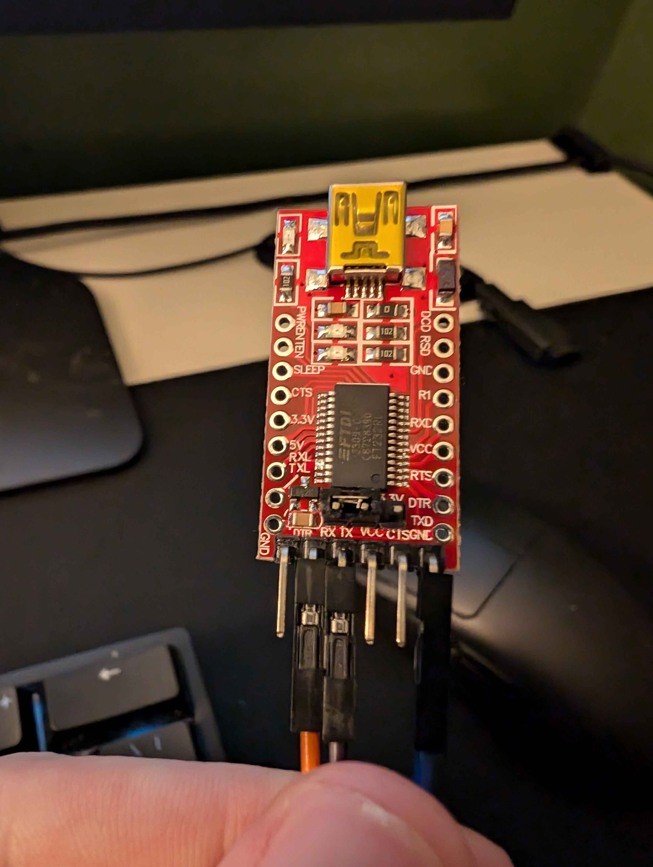
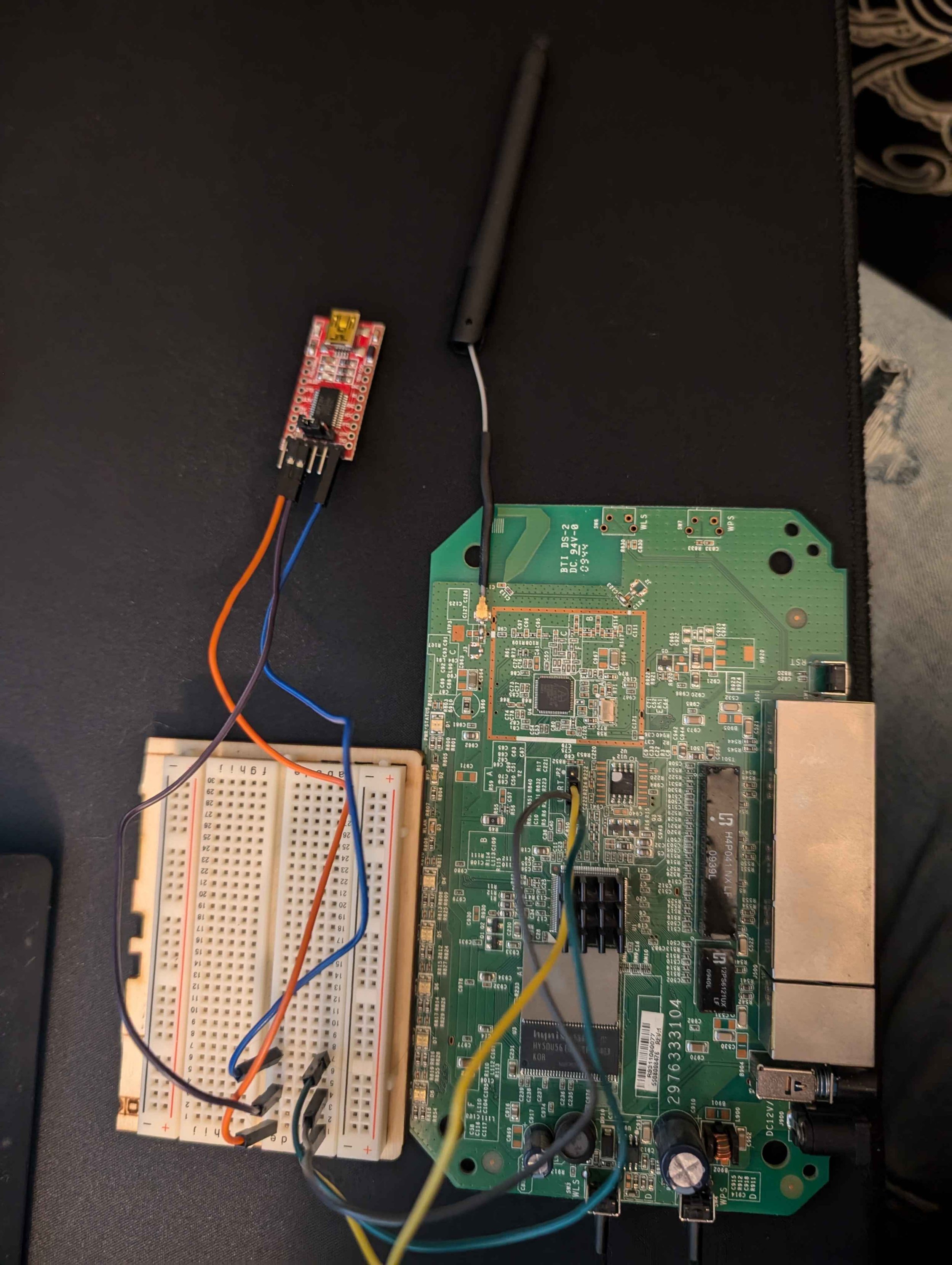
Top Left: From top to bottom it goes GND, Rx, Tx, VCC.
Bottom Right: Pad to the left of ATP3, identified as GND.
Recently, I’ve been seeing hardware hacking videos on YouTube, and this peaked my interest. So, I ordered a FT232RL on amazon and found an old Netgear WNR1000v2 collecting dust.
Tools Used
Fluke 87 III True RMS Multimeter
Screwdriver (security bits may be required)
FT232RL or equivalent UART Debugger
Breadboard (Optional)
Jumper Wires
PC (In my case windows 10 for OS, any should work although software used might change)
Disassembly
So in order to start you need to access to the UART decoder pin and this means exposing the PCB inside. For the Netgear WNR1000v2, you remove 4 hex screws underneath the little rubber feet pads.
Identifying Signals
Next up is the hardest part of the entire process, identifying signals. Before I jump the gun on this process you need to know what you are looking for. In this case to gain a shell we only need the GND, Tx, and Rx signals. While the router has a VCC, GND, Tx, and Rx pin on its UART interface, in this case we do not need the VCC signal. It’s important to note every pin varies in purpose from device so we need to know for certain what pin is responsible for each signal.
In some cases the signals/pins may be labeled, but for my specific circumstance I had to use a multimeter. If you are doing this yourself some fundamental electronics knowledge is certainly helpful. I began finding the easiest and most useful pin, GND. It is important to never take a resistance or continuity check on a live piece of equipment so ensure it is electrically isolated.
How I went about finding ground is just by going off the 12VDC power supply cable and found which of the two pins is ground. From here I did a resistance check to test pad to verify it was a GND pad as it was unlabeled. Then I put my black probe on the test pad, and put the red probe on each pin, making note of the resistance. In this case, the first pin I tested read 0Ω and he other three sat around 0.5-5kΩ. The first pin is my GND.
Next up, I need to identify Tx and Rx. If you are doing this, I ensured the device was always in a boot state here when taking readings, I did this ensure the device was transmitting, hoping it would make my life easier when differentiating between Tx and Rx. I struggled a bit and spent roughly 20 minutes to know for certain, but after some reading I was able to identify the two first try. Despite this a general rule of thumb will help, VCC will sit at around battery voltage (in this case it was 3.3V), and Tx and Rx will vary depending on the type of logic and what the device is doing. In this case I see its a 3.3V, so Tx will sit closer to it (around 2.4V range), and Rx should be around 1V range.
After Identifying the pins, it is as simple as connecting the router’s Tx —> debugger’s Rx, router’s Rx —> debugger’s Tx, and GND —> GND. Plugging the debugger into my desktop’s usb port I then opened PUTTY


Configuring PUTTY
Set the connection type to Serial
Change serial line to reflect the correct USB port
(If you have trouble identifying the COM port try unplugging it with device manager open, and plugging it back in.)
Set the speed to the baud rate you wish to test
Press “Open”, a terminal should open and be blank
Ensure all your wires are properly connected to the device’s UART and the debugger
Plug in the device
In this specific case, my baud rate/speed was 115200bps (bits per second)
Shell
If everything worked, the terminal should begin to populate with some characters. If your baud rate is incorrect just repeat steps 1-6, and update the baud rate to a common speed and try again. Once you get everything dialed in it becomes very apparent and you should be greeted with a terminal showing the boot process.
Here we can see we have root and the router is running BusyBox v1.4.2
This concludes the blog post, and I will be following up on this once I decide which direction to take this project.


